
Coordinate System#
For any IMU based application it is important that the Coordinate system (definition and orientation) is clearly defined. Otherwise, algorithms might use the wrong axis or defined calculations might not work at all (believe us, it happened to us too, … more than once). Therefore, before using any algorithm in mobgap, make sure that the coordinate system of your data matches our expectations.
In general, we differentiate between 4 different coordinate systems:
The IMU sensor frame, which represents the correctly aligned physical orientation where sensor axes (x, y, z) truly correspond to anatomical body directions.
The body frame, defined by the axis IS (inferior-superior), ML (medial-lateral), PA (posterior-anterior) and moves with the body/sensor.
The “normal” global frame, defined by the axis gx, gy, gz that is defined globally* and does not move with the sensor. (* the initial orientation is defined by the first sample of the data)
The body-aligned global frame, defined by the axis GIS, GML, GPA and that is fixed like the global frame but expressed in terms of body axis in the initial position.
All of these coordinate systems follow the right-hand rule and the direction of rotation defined by the positive direction of the angular velocity follows the right-hand “thumb” rule around the respective positive direction of the acceleration.
Below, we will go through the coordinate systems in the order in which you likely will encounter them when working with mobgap.
Figures for Quick Reference#

Overview over all 4 coordinate systems. Details below.#

Available transformation functions between the different coordinate systems.
To transform between sensor-fixed and global frames, you always need the orientation information.
This is usually provided by the orientation estimation algorithms.
The orientation estimation algorithms in mobgap support both sensor frame or body frame data as input.
You can then either use the orientation_object_ output and provide it to transform_to_global_frame or use the
rotated_data_ output that is already transformed to the global frame.
In both cases, input data in the sensor frame will lead to output in the normal global frame and input data in the body
frame will lead to output in the body-aligned global frame.
More details below.#
Body Frame#
The body frame is defined by the axis IS (inferior-superior), ML (medial-lateral), PA (posterior-anterior) and is simply a renaming of the sensor axes. The figure above shows the expected direction of the body frame axis. The naming of the axis/conversion of the sensor frame is as follows: - x -> IS (inferior-superior) - y -> ML (medial-lateral) - z -> PA (posterior-anterior)
In code, this transformation can be done by the to_body_frame function.
This will return a dataframe with renamed axis and the same index as the input data.
Note: This assumes your raw data already uses mobgap’s x, y, z axis naming convention.
Different IMU devices may use different axis labels or column orders, so you will need to
pre-process such data to match mobgap’s expected format before calling to_body_frame().
Most algorithms in mobgap expect the data to be in the body frame, so that they can easily work on the “upwards” or “forward” axis. Algorithms that would work in both the sensor and body frame, will usually accept both.
Sensor Frame#
The sensor frame represents the correctly aligned physical orientation where the sensor axes (x, y, z) truly correspond to the anatomical body axes (IS, ML, PA). We expect these axis directions to follow the directions of the MM+ sensor of McRoberts (when worn correctly), which is the primary sensor used in the mobilise-d project. In this correct orientation, the sensor (when attached correctly) has:
the x-axis pointing upwards (IS direction)
the y-axis pointing to the right (ML direction)
the z-axis pointing forward (PA direction)
When sensor mounting is known and controlled#
To use all functions and algorithms in mobgap, you need to make sure that your data follows the same conventions. This means, you likely need to define a rotation matrix that transforms your data into the expected coordinate system. This transformation is usually derived based on the known mounting orientation of your sensor. Have a look at the sections 3 and 4 in this guide in gaitmap for more information on how to do this.
When sensor mounting is unknown or may change during a recording#
If you don’t have any information about the mounting orientation of your sensor (i.e., unsupervised free-living setting), you can use the reorientation correction algorithm to detect and correct sensor orientation based on accelerometer patterns during walking. The algorithm operates in three stages: (1) identifies which device axis captures gravity (vertical acceleration), (2) determines the gravity direction (up/down) and rotates the sensor data so that gravity correctly aligns with the “assumed vertical”, and (3) uses cross-spectral phase analysis between vertical (after step 2) and posterior-anterior axes to determine correct mediolateral and posterior-anterior orientations.
For more details see the documentation of the ReorientationMethodDM class.
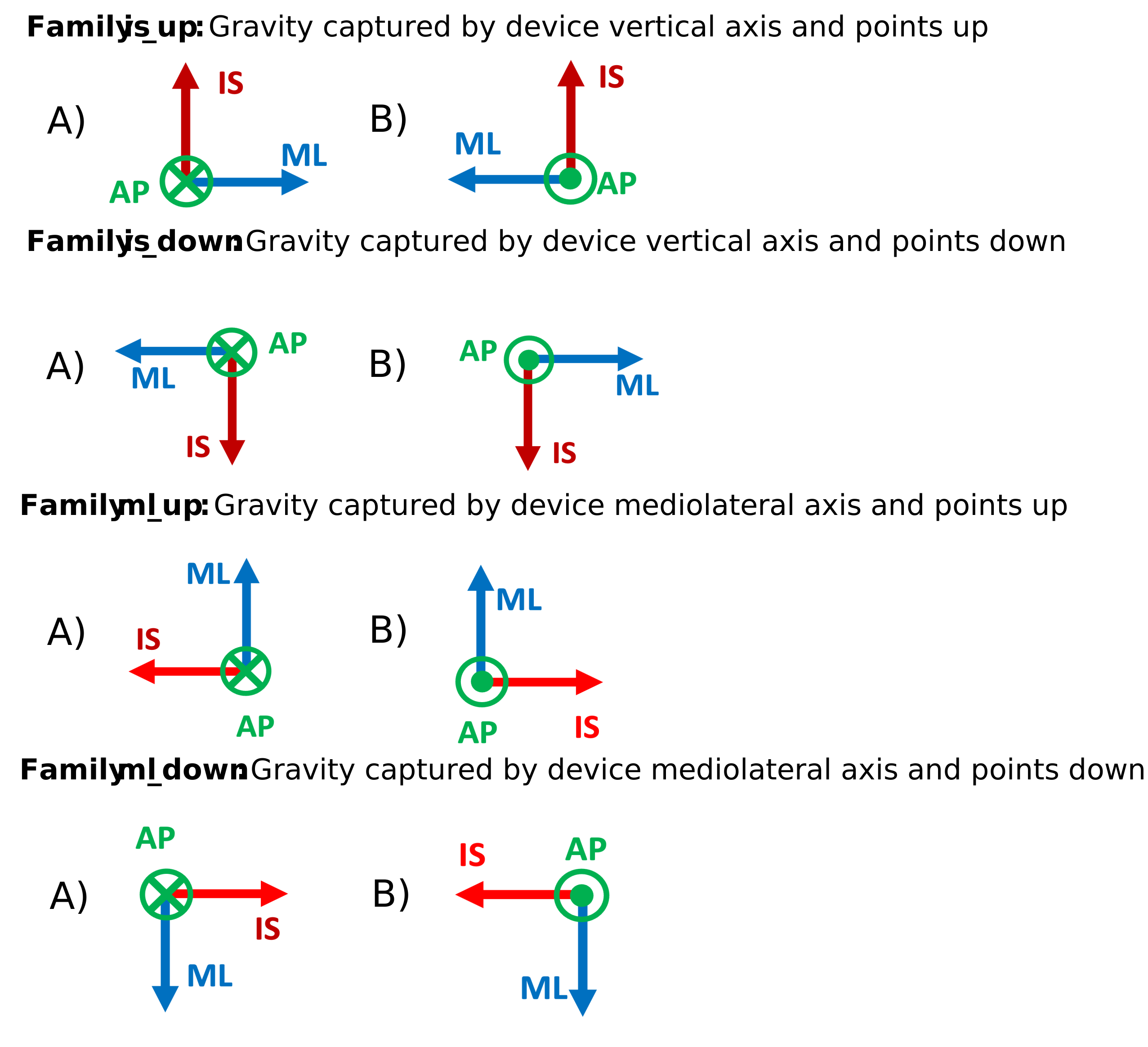
Figure. All possible device orientation families for a lower-back-worn IMU (belt-worn (Families is_up, is_down) and patch-attached (all Families)). Each panel shows a distinct orientation defined by which device axis captures gravity and its direction. Family “is_up” A (top-left) represents the correct reference orientation (IS up, ML right, PA forward). Boxes adjacent to each orientation indicate the rotation(s) of that device orientation from the reference frame: rot(x) = rotation around x/IS axis, rot(y) = rotation around y/ML axis, rot(z) = rotation around z/PA axis. Composite rotations (e.g., “180° rot(x) + 90° rot(z)”) indicate sequential transformations. The algorithm detects these families and applies the inverse rotations to restore the reference frame alignment. Within each family (i.e., “is_up”, “is_down”, “ml_up”, “ml_down”), two orientations differ only in ML and PA axis directions, determined through cross-spectral phase analysis. The green circle indicates PA direction: dot (•) = backward, cross (×) = forward. IS = infero-superior, ML = mediolateral, PA = posterior-anterior.
You can use the automatic reorientation correction incorporated in the pipeline (needs to be enabled manually) to align the sensor data to the body frame on a gait sequence level.
Note, that knowing the sensor mounting orientation is always preferable and provides more predictable results than attempting to correct for it after the fact. You should also only activate/use the reorientation correction if you really don’t have any information about the sensor mounting orientation. Activating the reorientation correction when the sensor data is already in the correct orientation can in rare cases lead to worse results, as the algorithm might detect a wrong orientation and apply a wrong correction.
Global coordinate system#
In addition to the body frame, we also define a global coordinate system. This coordinate system is fixed in space and does not move with the sensor or the body.
To transform data from the body frame to the global frame, you usually need to apply an orientation estimation
algorithm.
These are usually sensor fusion algorithm that combine the data from the accelerometer and gyroscope
(and potentially magnetometer or other additional modalities) to estimate the orientation of the sensor in a fixed
global coordinate system.
In mobgap, we provide an implementation of the Madgwick algorithm for this
purpose, but other algorithms can be used as well.
The global frame definition follows the commonly used axis definitions used in many sensor fusion algorithms:
gz -> upwards (i.e. gravity aligned)
gy -> left (i.e. extracted from the sensor orientation at t=0, note that this is the negative direction of the sensor y-axis/ML axis)
gx -> forward (i.e. the direction of movement extracted from the sensor orientation at t=0)
By following the most common definitions here, we hope to make it easier to use other sensor fusion algorithms with mobgap. However, as the axis definitions in the global frame are not directly defined by the axis in the sensor frame at t=0, some care should be taken when using other sensor fusion algorithms.
The initial sensor orientation in the global coordinate system should be set to the neutral orientation of the sensor frame:
import numpy as np

# Initial orientation of the sensor in the global coordinate system
R = np.array([[0, 0, 1],
              [0, -1, 0],
              [1, 0, 0]])
The quaternion values of this rotation matrix are [\sqrt{2}/2, 0, \sqrt{2}/2, 0] (in a (x, y, z, w) convention).
This value as scipy rotation object is available mobgap package as mobgap.consts.INITIAL_MOBILISED_ORIENTATION and
should be used as the initial orientation for any sensor fusion algorithm.
When working with IMU data projected into the global frame, you should always be aware that the axis definitions are
different from the sensor frame.
However, that makes it quite inconvenient to work with the data.
In particular for algorithm like TdElgohary that can either be used in a sensor-fixed or
global frame, and needs the axis pointing “upwards” in both cases.
Therefore, we introduce the body-aligned global frame.
Body-aligned global frame#
The body-aligned global frame is defined by the axis GIS (global inferior-superior), GML (global medial-lateral), GPA (global posterior-anterior) and is fixed in space like the global frame. However, the axis are defined in terms of the body frame axis. This allows to easily pick, for example, the axis that points “upwards” without remembering the global frame convention.
To transform between the global and body-aligned global frame, you can use the to_body_frame
function.
Further, to make the common usecase of transferring body-frame data to the body-aligned global frame easier, the
orientation estimation algorithms like the Madgwick algorithm allow to use
body-frame data (i.e., acc_ic, acc_pa, …) as input and return the data (self.rotated_data_) in the body-aligned
global frame, when body-frame input is detected.
Under the hood, this uses transform_to_global_frame that takes the orientation
estimation from sensor to normal global frame as input and correctly applies it to either sensor frame or body frame
data (see graphic above for more details).